Saturday 25 May 2013
Consider a wave propagating in Z direction. So the
components present are EX,EY,HX,HY
and the components EZ = HZ = 0
Polarization is not present in the direction of wave
propagation
Consider E = E1 cos (ωt-βz )aX +
E2 cos (ωt-βz+φ )aY
The wave is propagating is in positive Z direction
Where φ indicates phase difference between x and y
components of the field.
If φ = 0 then the wave is linearly polarized
If φ = 90, E1 = E2, then the wave
is circularly polarized
If φ = 90, E1 ≠ E2, then the wave
is elliptically polarized
If φ = some phase difference, E1 ≠ E2,
then the wave is elliptically polarized with an inclination equal to phase
difference
Example 1
E = sin (ωt-βz )aX + sin (ωt-βz+900
)aY
Solution
As there is a phase difference of 90 and E1
= E2, we can say it is circularly polarized
How to identify whether it is left or right handed.
First fix the orientation point by keeping propagation
direction = 0 ie., Z= 0
Now substitute ωt =0,90,180,270,360
When ωt = 0
E = aY
When ωt = 90
E = aX
When ωt = 180
E = - aY
When ωt = 270
E = - aX
Now
point your thumb finger in the direction of propagation and close your fingers
according to the components appear on the graph, which hand suits the closing
fingers with the direction of propagation gives left hand or right hand.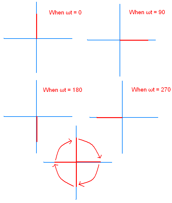
Positive Z direction upwards, negative Z direction
downwards.
For the obtained graph left hand suits. So it is left
circularly polarized.
Example 2
E = ( aX + 2 ej(∏/2) aY)
ej(ωt+βz )
Solution
Expand ejθ = cos θ + jsinθ
E =( aX + 2 ( cos 90 + jsin 90 ) aY)
*( cos (ωt+βz ) + j sin ( ωt+βz )
E =( aX + 2 j aY) *( cos (ωt+βz )
+ j sin ( ωt+βz )
Know take real part of E
E = ( cos (ωt+βz ) aX – 2 sin ( ωt+βz ) aY
Comparing with general expression of E
We can say that wave is going in negative Z direction
First fix the orientation point by keeping propagation
direction = 0 ie., Z= 0
Now substitute ωt =0,90,180,270,360
When ωt = 0
E = aY
When ωt = 90
E = -2 aX
When ωt = 180
E = - aY
When ωt = 270
E = + 2 aX
Draw the graph as above example
For the obtained graph left hand suits. So it is left
elliptically polarized.
Example 3
E = sin (ωt+βx)( aY + jaZ)
Solution
E = sin (ωt+βx) aY + sin (ωt+βx + 90)aZ
We can say that wave is going in negative X direction
When ωt = 0
E = aZ
When ωt = 90
E = aY
When ωt = 180
E = - aZ
When ωt = 270
E = - aY
Draw the graph as above example
For the obtained graph left hand suits. So it is right
circularly polarized.
Saturday 25 May 2013 0
Wednesday 15 May 2013
CURRENT LEVELS
IIH – High level input current: The current that
flows into an input when a specied high-level voltage is applied to that input
IIL - Low level input current: The current that
flows into an input when a specified low-level voltage is applied to that input
IOH – High level output current: The current that
flows from an output in the logical 1 state under specified load conditions
IOL– Low level output current: The current that
flows from an output in the logical 0 state under specified load conditions
VOLTAGE LEVELS
VIH - High level input voltage : The minimum
voltage level required for a logical 1 at an input.
VIL - Low level input voltage : The maximum voltage
level required for a logical 0 at an input
VOH - High level output voltage : The minimum
voltage level at logical circuit output in logical 1 state under specified load
conditions
VOL - High level output voltage : The maximum
voltage level at logical circuit output in logical 0 state under specified load
conditions
FAN OUT
The maximum number of standard logic inputs that an output
can drive reliably. If this number is exceeded, the output logic-level voltage
cannot be guaranteed.
PROPAGATION DELAY
There are two types of propagation delay
tPLH : delay time in going from logical 0 to
logical 1 state (LOW to HIGH)
tPHL : delay time in going from logical 1 to
logical 0 state (HIGH to LOW)
POWER DISSIPATION
It is the product of input voltage and input current
PD (avg ) = ICC( avg ) * VCC
ICC( avg ) = (ICCH +ICCL)/2
ICCH = the current drain when all the gate
outputs is HIGH
ICCL = the current drain when all the gate
outputs is LOW
NOISE IMMUNITY
It is defined as the ability of the circuit to tolerate
noise without causing spurious changes in output voltage.
Stray electric and magnetic fields can induce voltages on
the connecting wires between logic circuits. These unwanted spurious signals
are called noise and sometimes cause voltage at the input to a logic circuit to
drop below VIH(min) or rise above VIL(max)
HIGH state noise margin VNH = VOH (
min) – VIH (min)
LOW state noise margin VNL = VIL(max)
– VOL (max)
CURRENT SOURCING
When output of gate 1 is at HIGH state, it supplies a
current IIH to the input of gate 2 which acts as a resistance to ground.
Therefore output of gate 1 is acting as a source of current for gate 2.

CURRENT SINKING
When
output of gate 1 is at LOW state, it supplies a current IIL to the output
of gate 1 which acts as a resistance to ground. Therefore output of gate 1 is
acting as a sink of current for gate 2. 
Speed-Power product is called figure of merit
OPERATING
TEMPERATURE
The temperature
range in which an IC functions properly is a very important parameter. The
accepted temperature ranges are: 0 to +700C for consumer and industrial
applications whereas -55 0C to +1250C for military
applications.
Wednesday 15 May 2013 0
Friday 10 May 2013
It decreases the steady state error without effecting
the stability
Its transfer function is KP + KI
/ S = (KPS + KI)/S
PI controller adds one pole at origin which increases TYPE.
As TYPE increases steady state error decreases.
It also adds one finite zero in left of s-plane which
avoids the effect on stability
Example

Characteristic equation is S2 + 5S + 1=0
Applying controller

TYPE increases. So steady state error decreases
Characteristic equation S3 + 5S2
+ KPS+ KI = 0
All powers of S are there in above equation. So no
effect o stability
EFFECT ON DAMPING FACTOR
Characteristic equation is S2 + 5S + 1 =0
From the above characteristic equation
ξ=
2.5
After applying controller (S+ 5)/S
G(S) H(S) = 1/S2
Characteristic equation is S2 + 1 =0
ξ= 0
We can infer that there is a decrement in the value
ξ
As ξ decreases peak over shoot increases
From above calculations
1) Damping factor decreases.
2) Peak over shoot increases.
3) Rise time decreases.( To verify this substitute two
different values of ξ in Tr formula )
4) Bandwidth increases, since Tr is
inversely proportion to bandwidth.
5) Settling increases as it is inversely proportional
to ξ.( To verify this substitute two different values of ξ in Ts
formula )
6) Affect on gain margin and phase margin
GAIN
MARGIN
Example
Without controller

Solution
For ωpc
-180 = -90 – tan-1(ω)- tan-1(ω/2)
By solving above equation we get
ωpc =
√2 rad/sec
Gain margin = -20 log | G(s) H(s) | at ωpc
| G(s) H(s) | at ωpc = 1/6
Gain margin= 15.5 db
For simplicity for calculation I assume controller (s +
1)/s

For ωpc
-180 = -180 – tan-1(ω) - tan-1(ω/2)
+ tan-1(ω)
ωpc = 0
| G(s) H(s) | at ωpc = ∞
Gain margin= -∞
So,
We Can Infer That There Is A Decrease In Gain Margin
PHASE
MARGIN
Without controller

Solution
For ωgc
| G(s) H(s) | at ωgc = 1

ω4+2ω2-1 =0
finding roots we get ωgc = 0.6435
PM = 180 + angle (G(s) H(s) | at ωgc
= 180 -90 -
tan-1(ω/2)
= 90- tan-1(0.6435/2)
= 72.16
For simplicity for calculation I assume controller (s +
2)/s

For ωgc
| G(s) H(s) | at ωgc = 1
1/ω2
= 1
ω2 = 1
finding roots we get ωgc = 1
PM = 180 + angle (G(s) H(s))| at ωgc
= 180 -180
= 0
From
Above Two PM’s we can conclude that PM decreases
Friday 10 May 2013 0
Subscribe to:
Posts (Atom)


